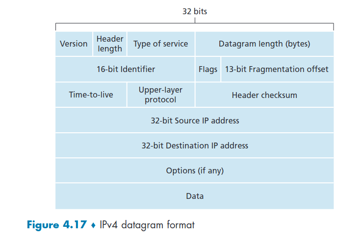
Version ->IP protocol version number (4) Type of Service -> TOS, ECN Length -> total datagram length (bytes) Time to Leave -> TTL -> max number remaining hops (decrement at each router) Upper Layer -> protocol to deliver payload to 20 bytes IP + 20 bytes TCP + app overhead 16-bit identifier, flags, fragment offset -> for fragmentation/reassembly Options -> timestamp, record route taken, specify list of routers to visit (for debugging) Data -> variable length, typically a TCP or UDP segment (can carry ICMP messages)
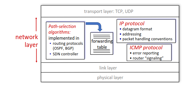
- Problem with Ip is that it contains fields that may not really be necessary. Has the header as like 40bytes, and the data could be way less than that.
4.3.2 IPv4 Addressing
- MTU (maximum transfer size) -> Largest possible link layer, can depend according to the link types. Different link types, different MTU
- Has IP datagram can be larger than the MTU, the message has to be fragmented. One datagram becomes several datagrams.
- The reassembly of this datagrams is done at the the final destination
- The IP header bits serve to identify the datagrams order when reassembling them.
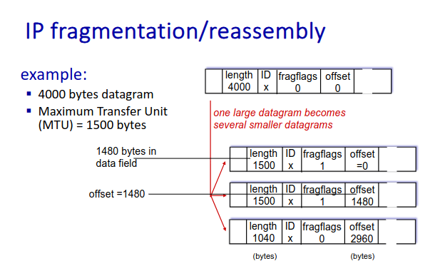
- If offset is little than it has to be multiplied by 8
- flag is zero if it is the last fragment
- IP header is 20 bytes, therefore the offset is at 1480, because that is the length of the actual data excluding the header
-
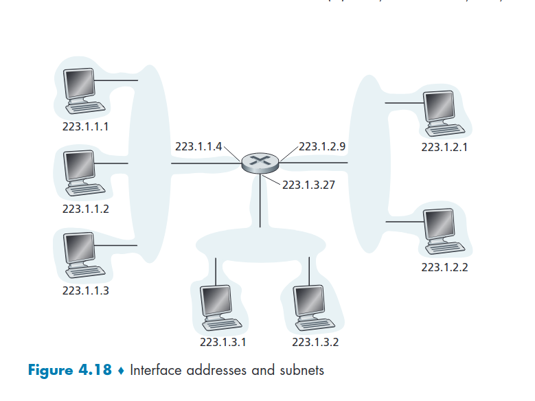
These four interfaces (223.1.1.X) are interconnected to each other by a network that contains no routers.
-
This network interconnecting three host interfaces and one router interface forms a subnet
-
IP address -> 32-bit identifier for host, router, interface.
-
Interface -> connection between host/router and physical link: - routers typically have multiple interfaces, one for each of their links - Host typically has one or two interfaces (wired ethernet, wifi) - Host with two or more active IP addresses is called multihomed
-
An IP address is technically associated with an interface, rather than with the host or router containing that interface.
-
IP addresses are associated with each interface, not a physical machine
-
Each network interface requires an IP address
Subnets
- Each isolated network is called a subnet
- Device Interfaces that can physically reach each other without an intervening router
- Interfaces on the same subnet have the same subnet address
- An organization (such as a company or academic institution) with multiple Ethernet segments and point-to-point links will have multiple subnets
- In the Internet, each IP address has to be unique, originally distributed in five classes ( classful addressing - A to E)
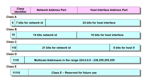
IP addresses have 4 bytes separated by dots X.X.X.X: - The subnet part occupies the high order bits - The Host part occupies the low order bits
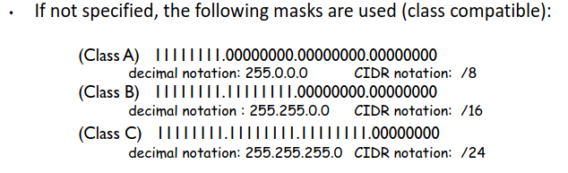
CIDR (Classeless Inter Doimain Routing): - used because classful addressing is not ideal since for example for an organization 8-bit mask may be small, but 16-bit is exaggerated. - EXAMPLE: A class C(/24) subnet could accommodate only up to 2⁸ - 2 = 254 hosts (-2 because two of the 256 addresses are reserved for special use)— too small for many organizations. However, a class B (/16) subnet, which supports up to 65,634 hosts, was too large and wasted many available addresses that could be used by other organizations. - subnet portion of address of arbitrary length - address format: a.b.c.d/x, where x(subnet mask) is # of bits in subnet portion address
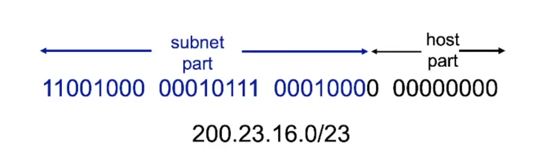
Example: 233.1.1.0/24 -> the 24(subnet mask) indicates the subnet part in bits 24/8(byte) is 3, meaning the subnet part consists of the first 3 bytes (233.1.1)
- Image 4.18 consists of 3 subnets {223.1.1; 223.1.2; 223.1.3}
- Only these x leading prefix bits are considered by routers outside the organization’s network. When a router outside the organization forwards a datagram whose destination address is inside the organization, only the leading x bits of the address need be considered, what helps reducing the size of the forward table.
- The remaining (lower bits) are used to distinguishing among the devices within the organization, all of which have the same network prefix.
Advantages :
-
allows better organization of the available addressing space
-
allows to establish hierarchical levels for routing (we’ll develop soon)
Costs : -
reduces the addressing space for host interfaces, as some of the initial addresses cannot be used with the same purpose.
-
requires additional addressing management
-
IP broadcast address (255.255.255.255) -> When a host sends a datagram with destination address 255.255.255.255, the message is delivered to all hosts on the same subnet.
There ar two ways a host gets an IP address - hard-coded by system admin in a file (Unix: /etc/rc.config) - dynamically gets addresses from a server (DHCP)
DHCP (Dynamic Host Configuration Protocol)
-
allows a host to obtain (be allocated) an IP address automatically when joining a network
-
A network administrator can configure DHCP so that:
- a given host receives the same IP address each time it connects to the network,
- a given host may be assigned a temporary IP address that will be different each time the host connects to the network
-
DHCP allows a host to learn:
- Its subnet mask
- The address of its first-hop router (often called the default gateway)
- The address of its local DNS server.
-
plug-and-play protocol, as it automates connecting to a host into a network
-
client-server protocol --> client -> newly arriving host wanting to obtain network configuration information, including an IP address for itself.
-
If no server is present on the subnet, a DHCP relay agent (typically a router) that knows the address of a DHCP server for that network is needed.
-
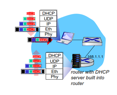
Typically, DHCP server will be located in router, serving all subnets to which router is attached
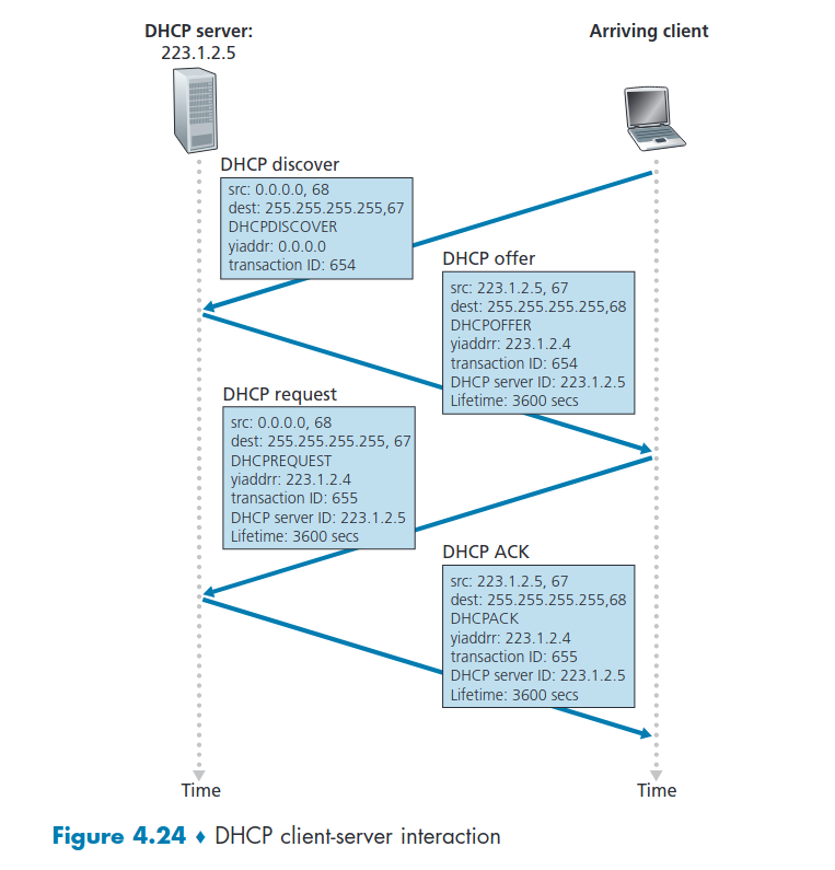
The DHCP protol is a four step process: - DHCP discover -> client sends DHCP discover message - DHCP offer -> server responds to the client with a DHCP offer message that is broadcast to all nodes on the subnet (through IP broadcast address 255.255.255.255) - DHCP request -> host requests IP address through DHCP request msg - DHCP ACK -> DHCP server sends address through DHCP ack msg
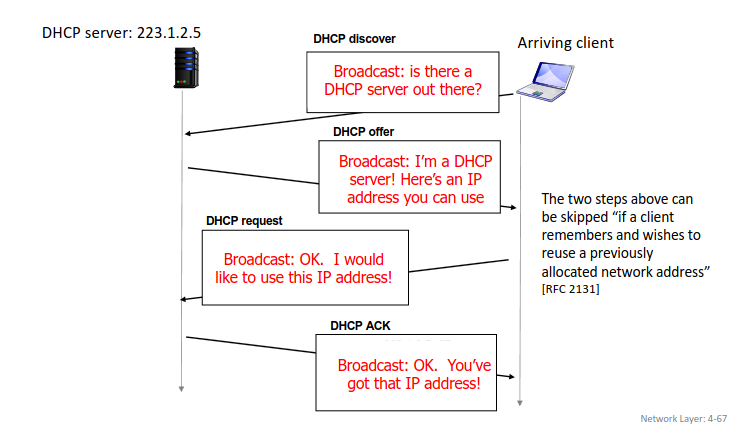
yiaddrr -> your internet address
- DHCP REQUEST message encapsulated in UDP, encapsulated in IP, encapsulated in Ethernet
- Connecting laptop will use DHCP to get IP address, address of first-hop router, address of DNS serve
Address Agregation
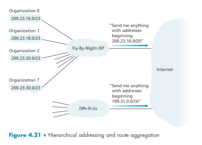
- Ability to use a single prefix to advertise multiple networks (subnets within subnets, also known as organizations)
- We don't send individual IP addressing advertisement, but an individual prefix IP addressing advertisement
- Fly-By-Night-ISP gets the packet from the Internet (200.23.26/20) and then distributes it through the 8 organizations
- This allows organizations from moving from one ISP to other without changing the physical IP addresses
- In Figure 4.2 ISPs-R-Us has a more specif route to Organization 1
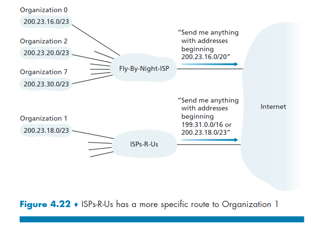
- Because of the longest matching prefix, the chosen packet is the one at 200.23.18.0/23
| IP |
|---|
| 200.23.26.0/20 |
| 199.31.0.0/16 |
| 200.23.18.0/23 |
- ISP's get block addresses from ICANN(Internet Corporation for Assigned Names and Numbers (non-profit organization)): -> allocates addresses -> manages DNS -> assigns domain names,resolves disputes
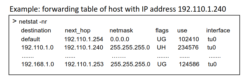
Forwarding Table
-
A netmask is used in IP networking to define which portion of an IP address refers to the network and which part refers to the host -> EX: IP: 11000000.10101000.00000001.00001010 (192.168.1.10/24) Netmask: 11111111.11111111.11111111.00000000 (255.255.255.0)
-
A subnet is a division of a network, not a separate network itself.
Collums:
-
1st: destination IP network (although forwarding per IP host address is also possible)
-
2nd: IP address of the host interface of next hop
-
3rd: netmask
-
last: interface id of the local link layer interface
-
other(depend on OS / implementation): flags, traffic volume, metric, etc.
-
Packet forwarding to next hop is decided based on IP destination address of the packet after applying the corresponding netmask.
Supernetting
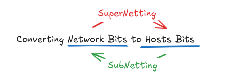
- Subnetting → creating multiple networks from a single bit network
- Supernetting or CIDR→ Combining of multiple Networks to Single Networks (Converting Netwroks Bits to Hosts Bits) - Aggregation
- Benefits: Reduces the network traffic and minimizes the size of routing table
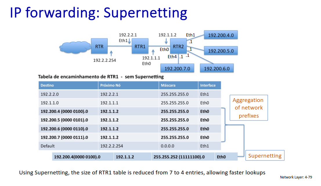
Step By Step: -> Write all numbers in binary -> Find matching bits left to write upto match ==.==
192.168.0.0/24 -> ==11000000.10101000.000000==00.00000000
192.168.1.0/24 -> ==11000000.10101000.000000==01.00000000
192.168.2.0/24 -> ==11000000.10101000.000000==10.00000000
192.168.3.0/24 -> ==11000000.10101000.000000==11.00000000
-> Write upto match and "0" upto end (New NID) ==11000000.10101000.000000==00.00000000 → 192.168.0.0/22 (New network Id) (22 because is the number of matching bits)
→ Make all "1" upto match and zero upto end (New Mask) ==11111111.11111111.111111==00.00000000 → 255.255.252.0 (New Mask)
Static vs Dynamic Routing (Control Plane)
Static Routing
- Based on routes defined manually or pre-defined in a configuration file
- reduces network traffic as no route advertisements take place
- simple scheme bit unable to accommodate network topology changes
Dynamic Routing
- router sends route advertisements to adjacent neighbors
- network traffic increases due to periodic anoucements or link changes
- flexible scheme, able to adapt to network topology changes or router failure
- common routing protocols: -> Distance Vector: RIP(Routing Information Protocol) (within an Autonomous System (AS), BGP(Border Gateway Protocol)(among AS)) -> Link State: OSPF(Open Shortest Path First)(Within an AS)
Routing Concepts (Control Plane)
- An Autonomous System(AS) is a set of IP routing prefixes under control of a single administrative entity or domain, that presents a clearly defined routing to the internet. -> eaxh ISPs has a unique AS number on the Internet -> EX: NOS(AS2860), Vodafone(AS12353)
- Routers may know multiple routes (static or dynamic) for the same IP destination. For that the criteria to choose which to choose considers distance(used among routes with different protocols) and metric(cost of forwarding traffic, used among routes with the same protocol)
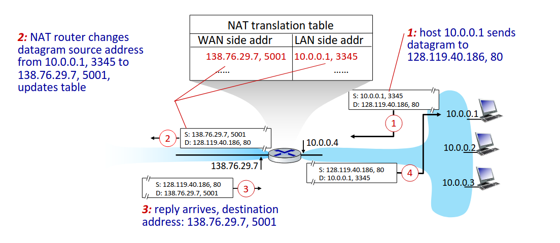
NAT: Network Address Translation
- As we are running out of IPs, NAT allows for all devices in a local network to share just one IPV4 address for the outisde world
- All datagrams leaving have the same NAT IP but different source numbers (PAT)
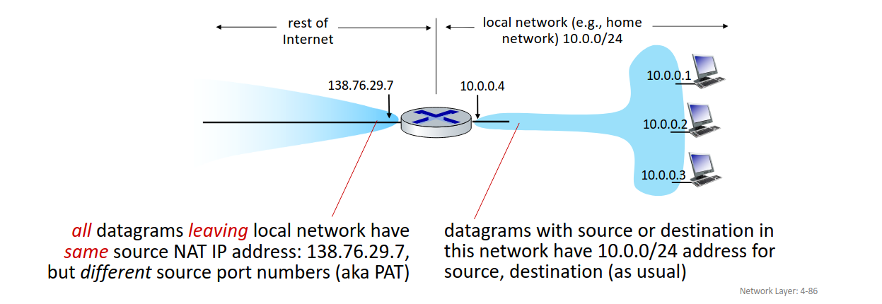
- We subscribe only for one IP address (global IP address) in the ISP, but in local network we create "fake" IP addresses/subnets (virtual IP address)
- As long as we use IP addresses in the local network everything is fine, but for outside of the network communication we have to use a NAT server sitting at the home gateway that assigns different ports to different devices so they don't colide.
Benefits:
- range of address not needed from ISP: just one IP address for all devices
- can change addresses of devices in local network without notifying outside world
- can change ISP without changing addresses of devices in local network
- devices inside local net not explicitly addressable, visible by outside world (a security plus)
Implementation:
- outgoing datagrams: replace (source IP address, port #) of every outgoing datagram to (NAT IP address, new port #). Replace fake IP address with global one and the source port number with the new port number
- remember (in NAT translation table) every (source IP address, port #) to (NAT IP address, new port #) translation pair
- incoming datagrams: replace (NAT IP address, new port #) in destination fields of every incoming datagram with corresponding (source IP address, port #) stored in NAT table
- 16-bit port-number for 65535 simultaneous connections with a LAN-side. Packets might be mistaken by other flows.
- NAT is controversial is that routers should only process up to layer 3 but NAT technically uses layer 4.
- NAT transversal: difficulty for packages coming from the outside to communicate with devices from the inside. Must be taken into account by app designers, P2P applications -> One layer protocols design has to have in consideration other layers, which violates end-to-end argument(modularization). Design in one layer should not bother about other layers(modularization).
IPv6
Motivation: -> IPv4 address space would be completely allocated -> speed processing/forwarding: 40-byte fixed length header no fragmmentation allowed -> enable different network-layer treatment of "flows"
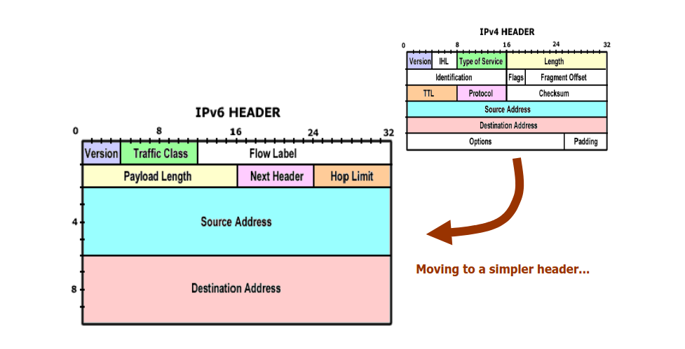
What’s missing (compared with IPv4):
- no checksum (to speed processing at routers)
- no fragmentation/reassembly
- no options (available as upper-layer, next-header protocol at router)
Tunneling
- IPv4 to Ipv6, the networks operate with mixed routers through tunneling
- IPv6 datagram carried as payload in IPv4 datagram among IPv4 routers
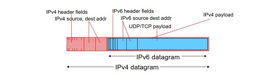
- Establishing tunnels between routers at the edge of IPv4 and IPv6
- Takes the IPv6 packet generated in IPv6 space and encapsulates it into IPv4 packet
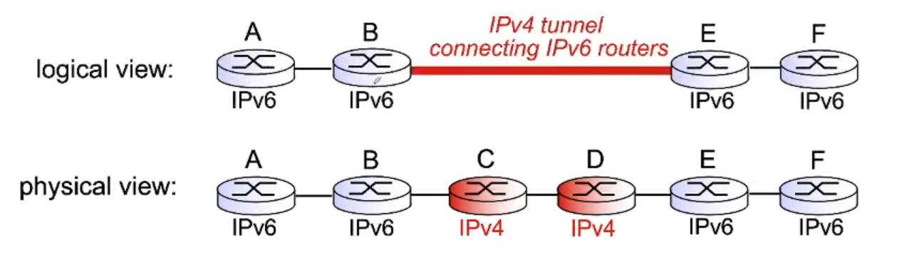
- In this case B encapsulates the IPV6 package into an IPV4 and E decapsulates it.
- A package is only sent in IPV6 if the last router, in this case F, must have IPV6 compability (checked by the DNS) if not the connection fails.
- Any link between routers is considered a different network