Packets -> smaller chunks of L bits of a long message broken by the source end system
- Between source and destination, each packet travels through communication links and packet switches (for which there are two predominant types, routers and link-layer switches)
Link Transmission Rate = capacity = bandwidth
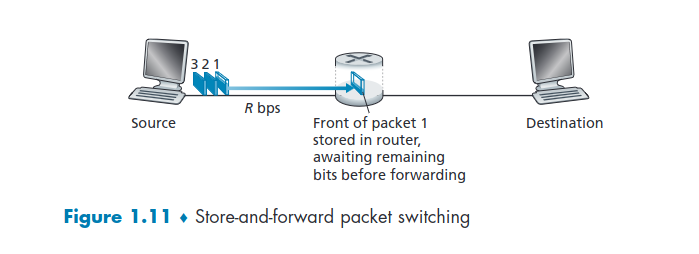
Time to transmit the packet = Packet Transmission Delay = L / R seconds -> L = packet bits -> Transmission Rate = R bits/sec
Store-and-Forward Transmission
- The packet switch must receive the entire packet before it can begin to transmit the first bit of the packet onto the outbound link.
Queuing Delays and Packet Loss
- Each packet switch has multiple links attached to it and each has an output buffer/queue, which stores packets that the router is about to send into that link.
- If arrival rate (in bps) to link exceeds transmission rate (bps) of link for some period of time: ->In addition to the store-and-forward delays, packets suffer output buffer queuing delays. These delays are variable and depend on the level of congestion in the network. ->This buffers are finite, so often times it gets full and packet loss occurs. This loss can be either for the latest packet arriving at the full buffer, or for an already in queue packet.
Forwarding Tables and Routing Protocols
- Packet forwarding is actually done in different ways in different types of computer network.
- The packet header includes the IP address of the destination end system.
- Each router has a forwarding table that maps destination addresses (or portions of the destination addresses) to that router’s outbound links.
- When a packet arrives at a router in the network, it examines a portion of the packet’s destination address and searches it's forwarding table finding the appropriate outbound link.
- The Internet has a number of special routing protocols that are used to automatically set the forwarding tables.
- A routing protocol may, for example, determine the shortest path from each router to each destination and use the shortest path results to configure the forwarding tables in the routers.
Analogy:
- A truck(packet) that wants to go from Oporto(source) to Lisbon(destination). Stops in a gas station(router) in Oporto to ask for instructions and the owner(forwarding table) recommends following the path to Aveiro and ask for more instructions there, and so on from one gas station to another until it gets to Lisbon.
1.3.2 - Circuit Switching
- Circuit-Switched Networks -> the resources needed along a path (buffers, link transmission rate) to provide for communication between the end systems are reserved for the duration of the communication session between the end systems.
- Packet-switched networks-> the resources are not reserved; a session’s messages use the resources on demand and, as a consequence, may have to wait (that is, queue) for access to a communication link.
Analogy:
-
Circuit-Switched Networks are like a restaurant that accepts reservations. You have the trouble of calling for a reservation but in counterpart you don't have to wait in line when getting there.
-
Packet-Switched Networks are like a restaurant that doesn't accept reservations. You don't have the trouble of calling for a reservation but in counterpart will have to wait in line for a seat.
-
Traditional telephone networks are examples of circuit-switched networks, before the sender can send the information, the network must establish a connection between the sender and the receiver.
Circuit-> the switches on the path between the sender and receiver maintain connection state for that connection.
- The network establishes the circuit and reserves a constant transmission rate in the network’s links.
- The sender can transfer the data to the receiver at the guaranteed constant rate.
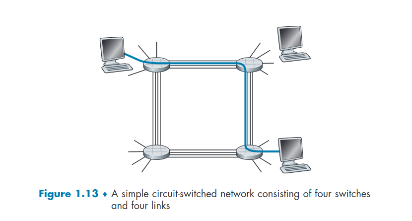
- As the image shows, that are 4 switches connected by 4 links. Each link has 4 circuits.
- When two hosts want to communicate, the network establishes a dedicated end-to-end connection, reserving one circuit on each of two links, between the two hosts that are directly connected to one of the switches.
- The connection gets one fourth of the link’s total transmission capacity for the duration of the connection given that are four circuits and it only uses one.
If we the telephone used packet-switched network, through the internet the connection might suffer some delay because of queuing, as with circuit-switching network it has a dedicated circuit to it.
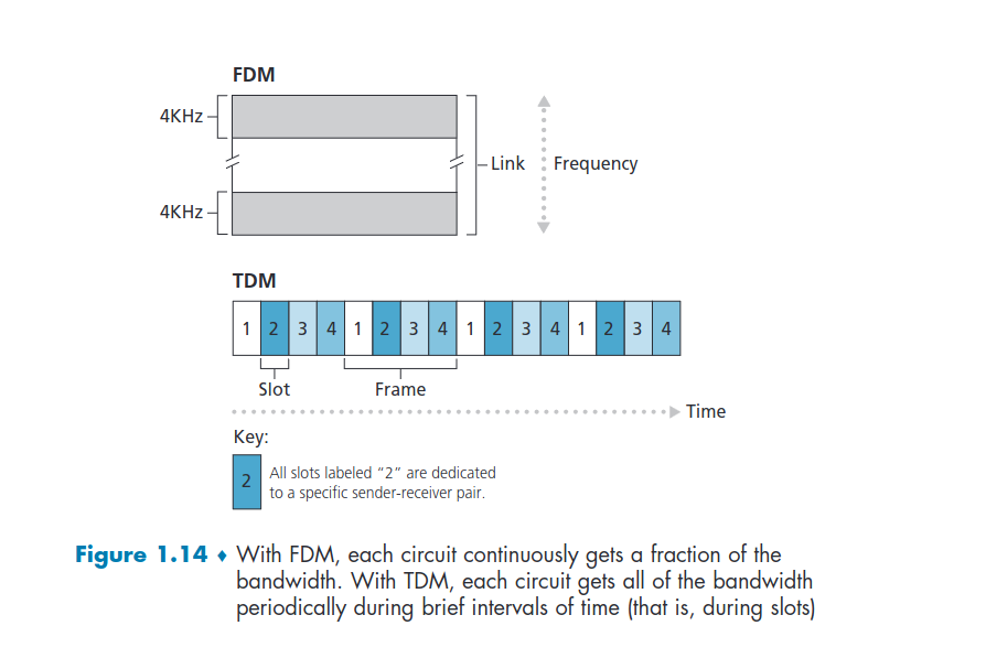
Multiplexing in Circuit-Switched Networks
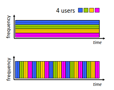
FDM(Fixed-Division Multiplexing) -> the frequency spectrum of a link is divided up among the connections established across the link. Specifically, the link dedicates a narrow frequency band to each connection for the duration of the connection.
TDM (Time-Division Multiplexing)-> time is divided into frames of fixed duration, and each frame is divided into a fixed number of time slots. When the network establishes a connection cross a link,the network dedicates one time slot in every frame to this connection. These slots are dedicated for the sole use of that connection, with one time slot available for use (in every frame) to transmit the connection’s data.
Each call allocated periodic slot(s), can transmit at maximum rate of (wider)
frequency band (only) during its time slot(s)
Packet Switching Versus Circuit Switching
Proponents of packet switching argue that
-> It offers better sharing of transmission capacity than circuit switching
-> It is simpler, more efficient, and less costly to implement than circuit switching.
-> circuit switching is wasteful because the dedicated circuits are useless during silent periods.
-
Packet-Switches show better performance than Circuit-Switches because reduce silent periods.
-
Some Circuit-Switching problems: -> Each user alternates between periods of activity(generates data) and periods of inactivity(when a user generates no data). With circuit switching the circuit is reserved at all time for a single user. Supposing that he is more inactive than active, then he's gate keeping a circuit that could be used by another. -> Consider a circuit-switched TDM that divides a link in 10 slots: - then it can only support 10 users simultaneously. - if only one user is active and wants to generate a lot of data then 9 slots are being wasted and that user's transmission rate could be way faster.
-
Packet Switching Pros: -> has pretty much the same performance of circuit-switching when the queue is not full, the packets flow without delay. -> When it is full however, even though delay exists and packets have to wait in line, it allows more users to access the internet. ->The active user can continuously send its packets at the full link rate, not wasting it with inactive users in their TDM slots.
-
Packet Switching provides essentially the same performance as circuit switching, but does so while allowing for more than three times the number of users.
-
Although packet switching and circuit switching are both prevalent in today’s telecommunication networks, the trend has certainly been in the direction of packet switching.
-
Circuit switching pre-allocates use of the transmission link regardless of demand, with allocated but unneeded link time going unused.
-
Packet switching allocates link use on demand.
1.3.3 - A Network of Networks
- Over the years, the network of networks that forms the Internet has evolved into a very complex structure. Much of this evolution is driven by economics and national policy.
- The overarching goal is to interconnect the access ISPs so that all end systems can send packets to each other. Network-core: -> Forwarding (switching) -> local action: move arriving packets from router’s input link to appropriate router output link ->Routing -> global action: determine source-destination paths taken by packets
Let's dive into the evolution of Internet Network Structure:
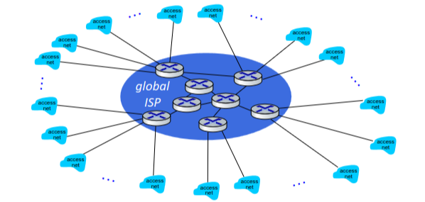
Network Structure 1
Interconnects all of the access ISPs with a single global transit ISP.
- This global transit ISP is a network of routers and communication links that not only spans the globe, but also has at least one router near each of the hundreds of thousands of access ISPs
- Would be very costly
- Customer and provider ISPs have economic agreement
- The access ISP is said to be a customer and the global transit ISP is said to be a provider
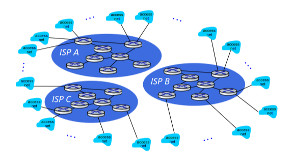
Network Structure 2
Hundreds of thousands of access ISPs and multiple global transit ISPs.
- If some company builds and operates a global transit ISP that is profitable, then it is natural for other companies to build their own.
- Two-tier hierarchy, with global transit providers residing at the top tier and access ISPs at the bottom tier
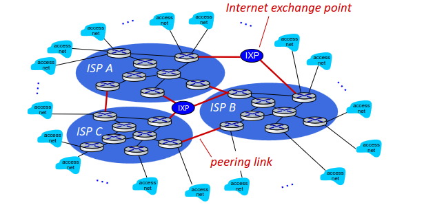
- However, that the global transit ISPs themselves must interconnect, otherwise access ISPs connected to one of the global transit providers would not be able to communicate with access ISPs connected to the other global transit providers. Trough: -> peering links -> Internet exchange points(IXP) -> in charge of non-profits or government so commercial companies do not dominate
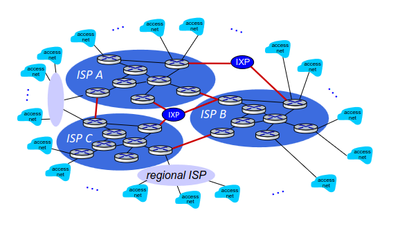
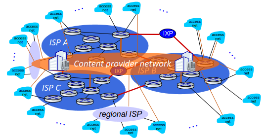
Network Structure 3
- In any given region, there may be a regional ISP(NOS, Meo, Vodafone,...) to which the access ISPs in the region connect
- Each regional ISP then connects to tier-1 ISPs (AT&T, Sprint, and NTT.).
- There may be multiple competing regional ISPs in a region. Each access ISP pays the regional ISP to which it connects, and each regional ISP pays the tier-1 ISP to which it connects.
- tier-1 ISPs do not pay anyone as they are at the top of the hierarchy.
- multi-tier hierarchy
- Some regions, there may be a larger regional ISP that connects to a tier-1 ISP(possibly spanning an entire country) to which the smaller regional ISPs in that region connect.
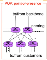
- Pop (points of presence)-> group of one ore more routers at the same location in the provider's network where customer ISPs can connect into the provider ISP. Normally pops are accessed by costumers trough a telecommunications provider
- PoPs exist in all levels of the hierarchy, except for the bottom (access ISP) level.
Network Structure 4
Content providers -> may run their own private network, to bring services, content close to end users (Google, Microsoft, Akamai, ...)
- Have data centers worldwide with thousands of servers.
- the number of machines and the connections they buy from the local ISP is comparable to a global ISP
- They are scale comparable to global ISPs, yet they are physically at a lower-level of hierarchy
- By creating its own network, a content provider not only reduces its payments to upper-tier ISPs, but also has greater control of how its services are ultimately delivered to end users.
Google example:
- Google private network attempts to “bypass” the upper tiers of the Internet by peering (settlement free) with lower-tier ISPs, either by directly connecting with them or by connecting with them at IXPs.
- Because many access ISPs can still only be reached by transiting through tier-1 networks, the Google network also connects to tier-1 ISPs, and pays those ISPs for the traffic it exchanges with them.
Summary
- End Systems connect to internet via access ISPs (Internet Service Providers) -> residential, company and university ISPs
- Access ISPs in turn must be interconnected -> so that any two hosts can send packets to each other
- Resulting network of networks is very complex -> evolution was driven by economic and national/business policies
Today's Internet Network Structure
-
Consisting of a dozen or so tier-1 ISPs and hundreds of thousands of lower-tier ISPs.
-
The lower-tier ISPs connect to the higher-tier ISPs, and the higher-tier ISPs interconnect with one another.
-
Major content providers have also created their own networks and connect directly into lower-tier ISPs where possible.
-
At the center: small # of well-connected large networks -> "tier-1" ISPs -> commercial ISPs (Level 3, Sprint, AT&T, NTT), national & international coverage. Connected to each other through peering links and IXP (may have direct connection to access ISPs). -> content provider network-> (Google, Microsoft, Akamai, ...): private networks that connects its data centers to Internet often bypassing tier-1, regional ISPs. Connect to the local ISPs (may connect with tier-1 for a fair price) -> Regional ISPs-> (Meo, NOS, Vodafone, ...)connect to tier-1 ISPs, cover regions and countries
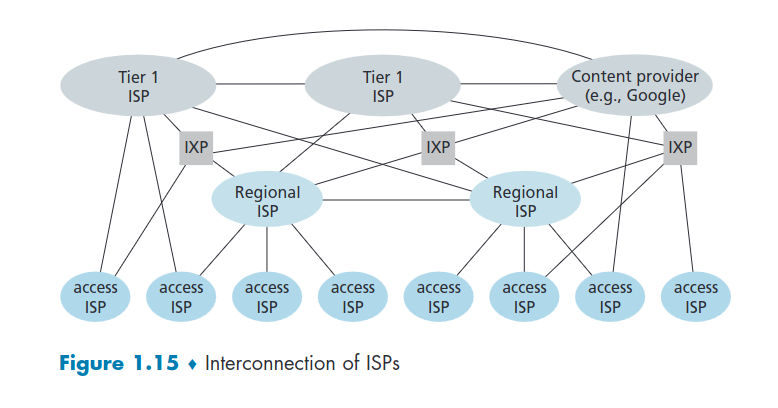
This image shows the most resourceful ones at the top and the least at the bottom.