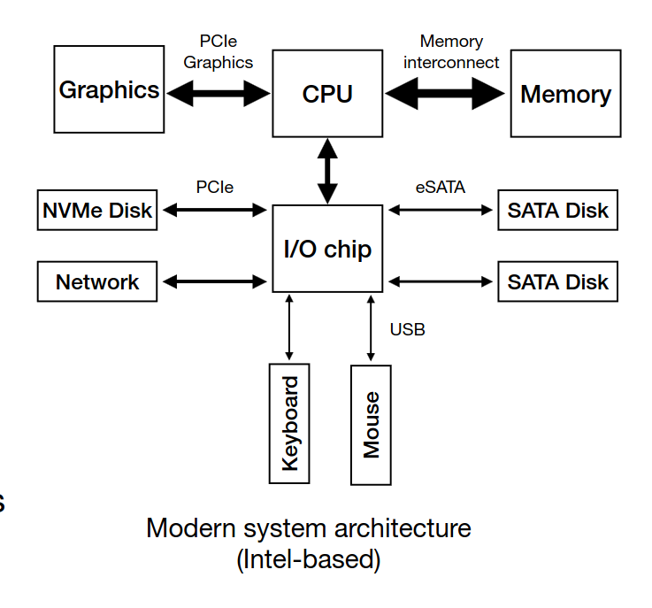
- CPU connects to an I/O chip through a Direct Media Interface (DMI)
- PCIe → fastest I/O BUS (EX: SSDs)
- eSATA → tradicional disks (EX: HDDs)
- USB → low performance devices (keyboaards, mouses, external drives)
-
A device has two components, interface and internal structure (hardware and firmware)
-
The device is controlled through three registers that are read and/or written by the OS
-> Status: holds the current status of the device
-> Command: holds commands to be executed by the device
-> Data: holds data to be written to or read from the device -
The OS repeatedly reads the status register by polling it
-
When the speed of the device is unknown or varies over time, a hybrid approach is used. Do some poll requests, but if the device is slow in serving the request, go for interrupts
-
Programmed I/O (PIO) → forces the CPU to stop other tasks just to copy data from memory to the I/O device (e.g., the device’s register)
-
The DMA engine is a specific device that is told by the OS where data is and where to copy it, orchestrating data between the I/O devices and main memory with little CPU intervention
-
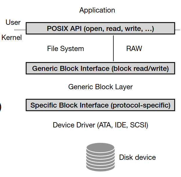
Device Driver Abstraction abstracts interfaces (Applications, file system, block layer)
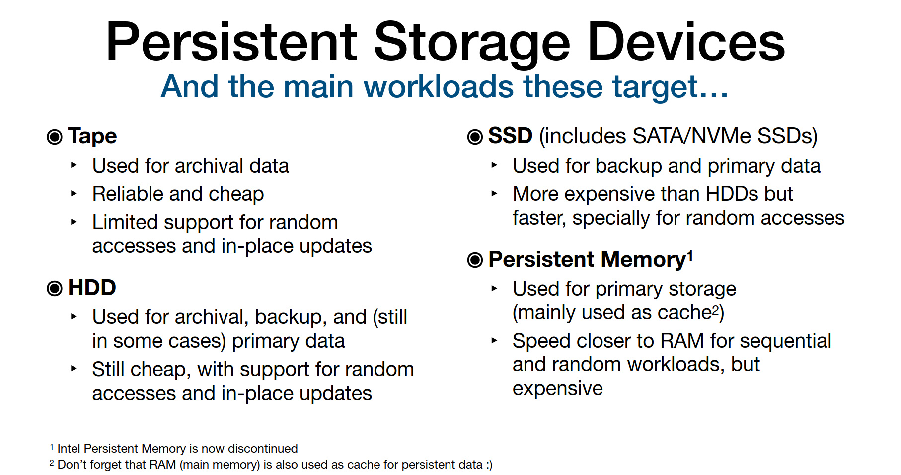
- The amount of available fast memory is smaller than the amount of slower capacity memory
- Storage types & workloads: ->Archival (Tape): append-only, low-latency not important ->Backup (HDD/SSD): sequential writes, occasional random access -> Primary Storage (SSD, Persistent Memory): fast, random/sequential, frequent updates
HDD
-
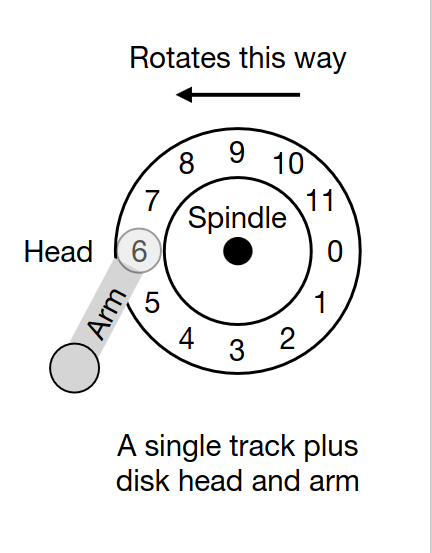
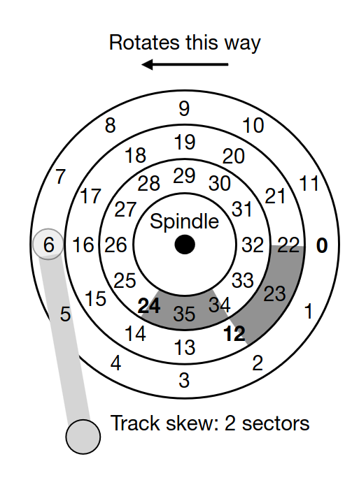
Data stored on spinning platters in tracks and sectors.
-
Performance factors: -> Seek time (move head to track) -> Rotational delay → Transfer time
-
The disk head is used to read or write a specific sector (one head per surface). The disk arm moves across the surface to position the head on the right track
- Disks usually have a small cache (e.g., 8, 16, 32 MB) to hold data read from or written to disk
- I/O time to read/write a given sector (TI/O):
T_{I/O} = T_{seek} + T_{rotation} + T_{transfer}
- Rate of the I/O:
R_{I/O} = Transfer_{ize} \: / \: T_{I/O}
- Sequential access = faster, random = slower
- Disk scheduling policies: -> SSTF (Shortest Seek Time First) - suffers from starvation -> SCAN / C-SCAN (elevator algorithm) - Move across the disk from inner to outer tracks (or the other way around)i.e., do a disk sweep -> SPTF (Shortest Positioning Time First)
- In disk scheduling, we can estimate the seek time and rotational delay of a given request, thus, having an idea of the time required to serve it
- I/O merging: Requests to contiguous sectors/blocks are typically merged by the OS before being sent to disk
- Therefore, in many cases, the OS waits (queues) some I/O requests from programs (i.e., it follows a non-work-conserving approach) before issuing these to the disk. Not issuing requests immediately (i.e., not following a work-conserving approach), allows for scheduling and merging optimizations
SSD
-
Based on NAND flash (no moving parts).
-
Bits are stored on transistors -> No arm seek time or head rotation time! -> No mechanical errors (e.g., head crashes)
-
Organized in blocks and pages.
-
Read = fast; Write requires erasing whole blocks (slower).
-
Erasing a block also wears out the lifespan of the SSD drive. Each block can only be erased and programmed a certain amount of times
-
Wear leveling spreads writes to avoid wearing out specific blocks.
-
Managed by Flash Translation Layer (FTL)(maps logical addresses (device interface) to the corresponding physical blocks and pages (flash chips)) and Garbage Collector (GC)(tracks unused pages and erases blocks).
-
Data structures for the FTL and GC, along with data caches, are kept on volatile memory (SRAM) at the device
-
Disks can fail: -> Fail-stop: disk dies entirely -> Latent Sector Errors (LSEs), corruption, misdirected/lost writes
-
Use checksums, ECC, scrubbing for early detection.
Redundant Array of Inexpensive Disks - RAID
-
Technique that uses multiple disks in concert to build a faster, bigger and more reliable disk system
-
Externally looks like only one disk - transparency
-
Internally requires multiple disks
-
RAID level 0: Blocks (e.g., 4KB) are spread across several disks in a round-robin fashion
-
RAID level 1: Blocks are copied across multiple disks (it can be combined with RAID level 0)
-
RAID level 4: Adds a parity disk. This disk holds a parity block (calculated with XOR) for each stripe of blocks
-
RAID level 5: Spreads parity blocks across the RAID disks
| RAID Level | Strategy | Pros | Cons |
|---|---|---|---|
| RAID 0 | Striping (RR) | Performance boost | No redundancy |
| RAID 1 | Mirroring | High reliability | 2x storage cost |
| RAID 4 | Parity disk | Efficient redundancy | Parity disk bottleneck |
| RAID 5 | Rotating parity | Balanced performance & redundancy | Only 1 disk failure tolerance |